Comtech EF Data CDM-600 Especificaciones Pagina 71
- Pagina / 90
- Tabla de contenidos
- MARCADORES
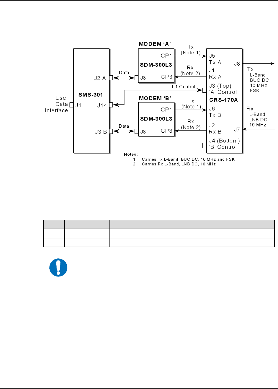
- L-Band 1:1 Redundancy Switch 3
- Table of Contents 5
- Figures 9
- Preface 11
- Preface MN/CRS170A.IOM 12
- Safety Compliance 14
- EN 60950 14
- Equipment Connection 14
- Environmental 14
- Low Voltage Directive (LVD) 15
- Warranty Policy 16
- Limitations of Warranty 16
- Exclusive Remedies 17
- Chapter 1. INTRODUCTION 19
- IMPORTANT 20
- 1.1.1 Modem Side Connectors 21
- 1.2 Functional Description 22
- Introduction MN/CRS170A.IOM 23
- • Safety 30
- Chapter 2. INSTALLATION 31
- 2.2 Mounting 32
- Chapter 3. MODEM AND SWITCH 33
- CONFIGURATION 33
- 3.2.2 Carrier-in-Carrier 34
- Redundancy Configuration 34
- IMPORTA T 38
- 3.6 SDM-300L3 Configuration 40
- Chapter 4. CABLES AND 43
- CONNECTIONS 43
- 4.2 Cabling to the CDM-625 44
- QTY Part No. Description 46
- SCSI-II) 47
- QTY Part No. Description 50
- 4.3 Cabling to the CDM-570L 53
- 1 4 CA/6357-4 54
- 4.4 Cabling to the CDM-700 59
- (CDI-60) Interface Kits 61
- (Multi-Mode) 63
- 4.5 Cabling to the CDM-710 65
- Chapter 5. CONNECTOR PINOUTS 73
- Appendix A. CABLE DRAWINGS 77
- Cable Draw 88
- METRIC CONVERSIONS 89
- 480 • 333 • 2200 PHONE 90
- • 333 • 2161 FAX 90
Relacionado con productos y manuales para Redes Comtech EF Data CDM-600
 (4 paginas)
(4 paginas)
(110 paginas)
(5 paginas)
(4 paginas)
(88 paginas)
(176 paginas)
(4 paginas)
(54 paginas)
(154 paginas)
(246 paginas)
(8 paginas)
(348 paginas)
(150 paginas)
(240 paginas)
(254 paginas)
(342 paginas)
(4 paginas)
(4 paginas)
(4 paginas)
(110 paginas)
(5 paginas)
(4 paginas)
(88 paginas)
(176 paginas)
(4 paginas)
(54 paginas)
(154 paginas)
(246 paginas)
(8 paginas)
(348 paginas)
(150 paginas)
(240 paginas)
(254 paginas)
(342 paginas)
© 2020, manymanuals.es. Todos los derechos reservados | 0.035 s |
 Manymanuals.com
 Manymanuals.de
 Manymanuals.fr
 Manymanuals.it
 Manymanuals.pl
 Manymanuals.cz
 Manymanuals.es
 Manymanuals-pt.com
Comentarios a estos manuales